Last Update: 13.11.2015
Out of curiosity and fun I wanted to build a mobile speaker as do-it-yourself project which can be fed with auxiliary music via line in from an iPod or cellphone or even directly use some SDcard or USB stick with MP3s on it. This should work with a single LiIon battery. So I went along and ordered a few cheap components.
Additionally, you need some more components like capacitors, resistors, power inductors and so on.
Push-Pull / class AB amp try-out
The PAM8403 PCBs took quite long to arrive, so I started building a push-pull-transistor amplifier for first tests - it's less efficient, but at least I could test if the rest of the setup works. (In fact a friend 'forced' me to do it, for learning/education sake; thanks Andre, it worked. I now see capacitors not solely as equivalent of a battery anymore, but also as a frequency dependant resistor. Well done, sir!)
As always, clicking on the pictures will increase their size.
The layout of the DIY Class AB-amplifier circuit.
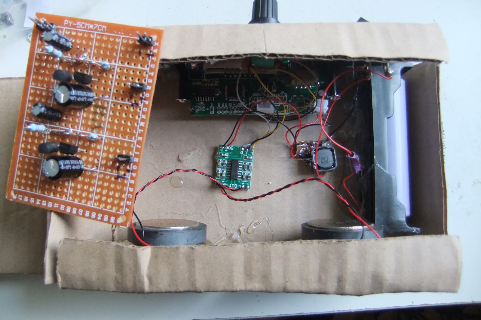
Top view - it's quite small, too! It's actually amazing how simple it is to build.
Some more photos and explanations from the build process:
The decoder board had a 78M05 low dropout regulator which I needed to desolder; I just bridged the remaining Vin/Vout terminals. The 5V supply stem from a small TD8208 step-up regulator. As it can deliver up to 2A, this will be enough for the 2 * 3W of the PAM8403 amplifier and the little supply current needed by MP3 decoder board. So the whole Boombox will run with a stable supply when using a LiIon cell.
The MP3 decoder output inspected via DSO toy oscilloscope. Vpp is bigger than 1V. And also notice: It works!
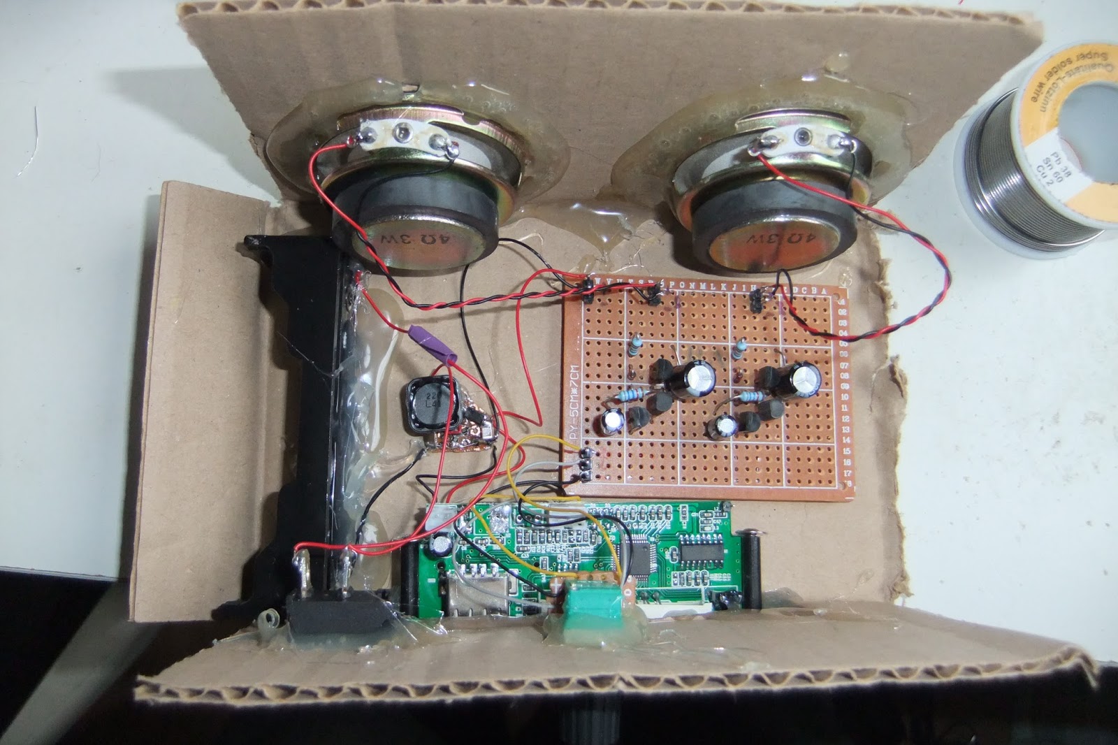
Since I lack craftmenship capabilities, I used simple cardboard for putting the stuff together so far. The output of the MP3 decoder passes through a 20kOhm stereo potentiometer so the output volume will be adjustable.
Hot glue is working very well to keep the components in place.
Since the step-up PCB and the MP3 decoder will draw small amounts of current even in off-mode, I added an on-off-switch between the positive terminal of the battery and the positive input of the TD8208 board.
Not pretty, but working. The display is running multiplexed at a quite low frequency, thus not the whole information is readable with a too short shutter time of the camera.
Then connected everything together. The best thing is it worked immediately! Well, kind of. The volume was a bit too low and the sound distorted. Reviewing everything I found that I soldered the PNP transistor the wrong way - it needs to be emitter against emitter. After that change - wow, that is loud! And the sound quality is nice, too. Except for the prominent hissing noise / white noise at low volume.
And then the PAM8403 PCBs arrived. Soldered one board in unmodified for a first fast test. Have a look at its small size compared to the AB-amp!
So the first draft version of the Boombox can be closed now. This is the front view. Need to decorate it a little, it already looks a bit like No. 5 or Wall-E :)
And this is the back view. I added some Velcro to 'the lid' so the battery can be easily accessed. But since I plugged the cell in a few days ago, its voltage just dropped by 0.2V to 3.9V even with prolonged usage (with the AB amp before as well, no recharge done since plugging it in the first time). The circuits thus are very efficient.
According to the PAM8403 datasheet, even if the Class D amplifier is working filterless, some components should be added to reduce EMI. In all cases, the power supply should have added capacitance of about 1000µF. I didn't want to add electrolytic capacitors as they tend to age, so I used two additional 100µF ceramic capacitors in parallel.
Next Diodes Inc. suggests to use ferrite beads in the lines to the loudspeakers and also 220pF capacitors to ground. This shouldn't be needed for wires less than 20cm long, but well - I don't want to disturb the neighbourhood with a 2*3W sender (the PAM amp switches with 260kHz and the harmonics of this frequency will be disturbed).
Update 25.09.2015: Now with some denoising - the signal lines to and from the potentiometer were receiving noise from other components. The MP3 decoder board isn't shielded at all, so over a layer of capton tape I added some copper foil and soldered it to GND as well, like the copper foil around the potentiometer wires. The PAM8403 PCB got 100µF and 10µF additional ceramic capacitos for proper decoupling. The GND and positive connections of the step-up-boards are done via ferrite beads. The cables for the GND and plus connections of the TD8208 stepup are thicker now. An additional step-up (BL8530) now supplies power to the MP3 board and is fed directly from the LiIon battery as well. This leads to massively less noise. Make sure to have some shielding in place and make the wires as short as possible.
Oh, and using a CD75 4,7µH power inductor instead of the 22µH for the TD8208 decreases noise quite a lot. The datasheet just has some complex formulas for calculating a suitable dimension and makes no suggestions about the proper range for the inductors.
Next step for improvement is a so-called Pi filter between the step-up boards and the periphery. This is a simple solution with ferrite beads, where I added 1µF ceramic capacitors between the + and - lines - one before and one after the ferrite. This helps filtering quite a lot of humming and noise, too.
Now I'm satisfied as the sound quality is very acceptable for a mobile MP3 speaker.
Update 03.10.2015: Finally, the improved wooden version of the PAM8403 mobile Boombox in action. Please bear in mind that the cellphone microphone doesn't have adequate frequency response and the real sound is different, it is actually really good. Depending on the location where you put the box the sound even improves as the sound body will be extended. On a closed bucket, the bass is much more pronounced, for example. The box is loud enough to fill a huge room like kitchen or living room so that the people in there need to shout in order to understand each other! :)
Update 30.09.2015: Today my new saw, some glue for wood and some wood arrived. As the proof-of-concept works, it is time to make a more solid enclosure. Now waiting for the glue to dry so I can continue. :)
Update 01.10.2015: And now nearly finished. Everything is working and the sound significantly improved.
Still no real beautiful design object, but far better than being made only out of cardboard.
Only little left on the todo-list. Fix the battery, add a USB-charger (I think I have a few ;) ). And maybe make a lid from wood to, either to slide in or to flip.
Update 02.20.2015: Done. Charger works. Cotton / wool filling for the empty space to dampen the backward reflections of the speakers massively improves the sound. Unbelievable what this little sucker spits out now. Defined bass, clear heights, very transparent sound. Only a proper lid is missing, it currently is improvised with cardboard again - which is ok, but ... :)
Update 04.10.2015: First real-life test on a big open soccer field. Training for a choreography in dog school, the DIY Boombox had to take care of the music. In 50m distance it was still nicely audible. After two hours of straight usage, the battery voltage fell to 4.04V, starting from 4.14V. That is only very few percent of the battery's capacity (you have to keep the discharging curve of a LiIon battery in mind). Amazing!
And now with a proper lid. Finished! :)
Update 13.11.2015: I'll build three boom boxes - at least, now that several speakers lie around here. This is a Boombox made with Peiying PY-1010C. allegedly RMS 60W. Fed with PAM8403 currently gives nice bass and it is really loud. Have some 2x15W PAM8610 in the reception pipeline, also a TDA7492 amp. For the TPA3116D2 I have some better Blaupunkt GTx 542 SC; that will get a blog article of its own though as the power supply will be interesting there.
Of course, a clip of this beauty at work is available, too. This is during the first test.
I've been busy measuring a few more charge cycles of some LiIon chargers.
LiitoKala Lii-260
Nitecore D2
Efest Bio V2
Xtar WP2.2
Soshine T2
Xtar MC0
TP4056
TP4057
LTC4054
SE9017
AP5056
MCP73831
ME4057D (4.35V!)
SE9016
It's funny that the single IC solution seem to give the most appropriate result as they properly deliver a CC-CV charging scheme, while the commercial chargers all implement some kind of trickle charging where they charge for a few seconds and then stop for measurements. This seems unnecessary as it prolongs the charge cycle and is all but constant current. This should be no problem as LiIon chemistry copes well with starts and stops during charging, but I prefer the "proper" implementation.
Update 30.06.2015: I finally received my first external ADCs with higher resolution. I'm replacing the graphs with their 16 bit ADC representation one by one. So far the ADS1115 has been used with the LiitoKala Lii-260 and the TP4057. Other (and more) chargers are in the pipeline.
Update 11.07.2015: Added the SE9017 charger IC. It is absolutely similar to the TP4057 from the datasheet and pinout, but can deliver higher charging current.
Also replaced the plot of the LTC4054 IC with a 16 bit ADC measurement.
Update 12.07.2015: Replaced the Xtar WP II graph with a 16 bit version. Also the TP4056 and the Xtar MC0 plot. Update 13.07.2015: Replaced the Soshine T2 graph with a 16 bit version. Update 15.07.2015: Added a new charger IC - the AP5056. Interesting charging curve! Update 17.07.2015: Added the Nitecore D2 and the Efest Bio V2 chargers which Max (Discordian) sent over. The Nitecore looks like a charger to avoid. Update 26.07.2015: New charger IC ME4057D arrived. It's a good charger for 4.35V LiIon batteries. Also added a charger from Microchip, the MCP73831. It's slow but very solid! Update 26.09.2015: Added the SE9016-IC; it's supposed to be a LTC4054-replacement and beats that IC by far.
For the Voltage-Ampere-Meter based upon my tiny STM32F030P4 boards I needed to measure different sources - two external sources and the supply voltage. Now from the datasheet, the samples on the net and in the Standard Peripheral Lib, all you need to do is to configure the channels you want to measure and that's it. But as soon as I wanted to measure more than one source, I got weird results. Research on the net gave no good hints where to look for the error.
The 12 bit ADC from ST knows some different ways to work: single shot measurement or continous mode, one channel or more channels. As soon as more than one channel is configured, it seems the ADC goes into the scanning mode where it measures each channel by subsequent ADC-Start commands. So if you want to measure your supply voltage in the beginning and later on something on Pin A0, every second call for an ADC conversion will measure Vcc instead of Pin A0. At least that would explain the results delivered in my tests.
To do it right, you need to DeInit the ADC after the measurement and for a new measurement completely re-initialize it. This leads to reliable and reasonable results. So here are some code snippets to show how I solved that for me.
 int read_vbat(void) {
      uint32_t temp = 0;
      adc_init(ADC_Channel_0, ADC_SampleTime_28_5Cycles);
      // throw away first result like on AVR? first value seems wrong.
      ADC_StartOfConversion(ADC1);
      while(ADC_GetFlagStatus(ADC1, ADC_FLAG_EOC) == RESET);
      for (uint8_t i = 0; i<8; i++) { // resampling
           ADC_StartOfConversion(ADC1);
           while(ADC_GetFlagStatus(ADC1, ADC_FLAG_EOC) == RESET);
           temp += ADC_GetConversionValue(ADC1);
      }
      ADC_Cmd(ADC1, DISABLE);
      return ( (temp>>3) );
 }
 int read_shunt(void) {
      uint32_t temp = 0;
      adc_init(ADC_Channel_1, ADC_SampleTime_28_5Cycles);
      // throw away first result like on AVR? first value seems wrong.
      ADC_StartOfConversion(ADC1);
      while(ADC_GetFlagStatus(ADC1, ADC_FLAG_EOC) == RESET);
      for (uint8_t i = 0; i<8; i++) { // resampling
           ADC_StartOfConversion(ADC1);
           while(ADC_GetFlagStatus(ADC1, ADC_FLAG_EOC) == RESET);
           temp += ADC_GetConversionValue(ADC1);
      }
      ADC_Cmd(ADC1, DISABLE);
      return ( (temp>>3) );
 }
 void read_Vdda(void) {
      // Get Vdda
      adc_init(ADC_Channel_17, ADC_SampleTime_28_5Cycles);
      ADC_VrefintCmd(ENABLE);
      ADC_StartOfConversion(ADC1);
      while(ADC_GetFlagStatus(ADC1, ADC_FLAG_EOC) == RESET);
      int temp=0;
      for (uint8_t i = 0; i<8; i++) { // resampling
           ADC_StartOfConversion(ADC1);
           while(ADC_GetFlagStatus(ADC1, ADC_FLAG_EOC) == RESET);
           temp += ADC_GetConversionValue(ADC1);
      }
      Vdda=(temp>>3)*3300/(VREFINT_CAL); // VREFINT_CAL/VRefInt=3300/Vdda -> Vdda=3300*Vref/VREFINT_CAL
      ADC_VrefintCmd(DISABLE);
      ADC_Cmd(ADC1, DISABLE);
 }
 void adc_init(int channel, int sample_time) {
      ADC_InitTypeDef ADC_InitStructure;
      ADC_DeInit(ADC1); // clean up
      ADC_InitStructure.ADC_Resolution = ADC_Resolution_12b;
      ADC_InitStructure.ADC_ContinuousConvMode = DISABLE; // on demand
      ADC_InitStructure.ADC_ExternalTrigConv = ADC_ExternalTrigConv_T1_TRGO;
      ADC_InitStructure.ADC_ExternalTrigConvEdge = ADC_ExternalTrigConvEdge_None;
      ADC_InitStructure.ADC_DataAlign = ADC_DataAlign_Right; // 12 bit right aligned
      ADC_InitStructure.ADC_ScanDirection = ADC_ScanDirection_Upward;
      ADC_Init(ADC1, &ADC_InitStructure);
      // ADC calibration; but not used as returned value ends nowhere now...
      ADC_GetCalibrationFactor(ADC1);
      ADC_ChannelConfig(ADC1, channel, sample_time);
      ADC_Cmd(ADC1, ENABLE);
      ADC_DiscModeCmd(ADC1, ENABLE);
 }
It seems necessary to split every channel reading into separate functions. Another solution would be to always read through all configured channels and update their values. For oversampling, that would mean quite some overhead if you don't need all those channels at that time.
Other observations: Although the STM32 ADCs have an internal voltage reference and even store their values measured at the factory at 30°C and 3.3V - you can only use that for calibrating. You can measure the actual VRefInt value and calculate your supply voltage based upon that. Which is in case of STM32F030P4 always your ADC reference voltage; this TSSOP20 µC lacks a Aref Pin. The address is different for different STM32 µC families - for STM32F030P4, you can read the factory calibration data like this:
   const uint16_t *p = (uint16_t *)0x1FFFF7BA; // 2 Byte at this address is VRefInt @3.3V/30°C
   VREFINT_CAL = *p; // read the value at pointer address
Before converting a channel with my desired signals I always call the function to read Vdda as well as the supply voltage may be unstable. This way, the results will get even more stable. Finally I can use the STM32 ADC - before finding out these weird behaviours it delivered mostly garbage. Now it's nearly a 12bit presision instrument ;)
TP4056 Charger plotted with STM32 ADC.
This is how a proper measurement cycle looks like in the end. Way better than with AVR / Arduino 10 bit ADC.