I still need to learn a lot in electronics. Just yesterday I accidentally connected the battery wrong to my LDO XC6206 - which it seriously disliked and afterwards spat out 0.56V instead of 3.3V. No problem, I have plenty of them in the box - but this may happen more often and I don't want to always solder in a new LDO.
So I looked for ways to protect the IC from wrong polarity of the battery. Since I power a ATmega328 based 7-segment-LED watch via a LiIon battery this way which needs around 2mA current, a usual diode is no alternative. The voltage drop of ~0.7V is not usable with LiIon (3.0-4.2V) on a 3.3V LDO. A Schottky diode would be way better with only 0.3V voltage drop, but still makes quite some capacity of the LiIon unusable.
Thus I decided to use the AO3415A P-channel MOSFET. It has to be connected with Drain to the battery, Source to the Vin of the LDO. Gate connects to Ground. Since the LiIon voltage is well within the specs of the AO3415 for Vgs(max), I can even work without a Zener diode/TL431 to limit the voltage; a resistor at the Gate seems not necessary as well. This is a unusual orientation for a P-FET, the first time I soldered it in without turning it on its back ;)
The results are better than I expected. The battery has 4.171-4.172V; on Source, I measure the same value down to the millivolt.
How does this protection work? When connected correctly, the body diode is conducting from Drain to Source. The Gate gets negative compared to the Source, the FET opens fully. The resistance drops down to Rds(on) for the current voltage. The load is so little with ~2mA that there is no significant voltage drop, it should be in the nano- or micro-volt area.
The capacitance behind the FET is quite small and should pose no risk that the FET wouldn't disconnect. If the battery is connected the wrong way, no current can flow as the body diode of the P-FET will block in that direction. The XC6206 won't be destroyed anymore. With such a cheap transistor the power supply is much more reliable.
I had some spare time during my vacation so I finally built a more solid version of my shunt and voltage divider "breakout" board which I used to measure the performance of LiIon chargers with.
I soldered everything onto a small breadboard and adopted the programming a little ...
Improved Data Logger for Charger Measurements.
As you can see, the plenty of loose cables are gone. Everything is statically soldered together so that no distortions should be possible anymore.
During the first tests, some error spots are still left. The two DuPont cables that lead from the charger to the board don't make solid contact, need to solder my own ones. And when moving the plugs in the USB ports of the computer, the voltage and current delivered are changing a little as well.
The first test: The DuPont cables for connecting
the charger need to be replaced.
But the main goal was to minimize other distortions and that worked great. I now use a 10 mOhm resistor which can stand 1W of heat dissipation and has a <= 1% error. The ADC (ADS1115) is connected via 10 kOhm resistors to its ends, ensuring very little bias. The voltage divider consists of two 100 kOhm resistors, where the connection to the ADC has again a resistor of 1 kOhm. The OpAmp for fetching the amplified differential voltage from the shunt is removed, I'm now using the built-in PGA of the ADC to get a good resolution. 1mA current over the shunt equals 10 µV, while the resolution of the ADC is ~7µV. I should probably add some oversampling as this signal has true noise and can improve this way.
Update 22:00h: Soldered wires with better contact to the board. This helped the resistance of the whole circuit to drop by 10% to now ~90 mOhm (including the battery with its inner resistance).
Also used a USB hub so only one connection is used on the computer. Turns out that the plugs show similar behaviour on the hub when the computer is moved - you can clearly still see every movement test.
The charger seems to get even less disturbed looking at the charging curve. >1A until 4.20V are reached and then the current drops slowly, while the voltage rises up to 4.25V for a short time. This is all within LiIon specs and looks quite nice.
Last updated 01.01.2016
I recently ordered a small Wifi bridge/repeater dongle which I wanted to use to offload the WPA2/AES encryption from my satellite receiver and have it connected virtually by ethernet. This Vonets Mini300 can't cope with long WPA passwords though with special characters - a "+" sign gets stored as space, thus it won't connect to my WLAN. The firmware was quite outdated and the update servers have changed, so the internal update mechanism doesn't work. The black and red wires are for a serial console to access the operating system on the little box directly and to see if it is possible to fix via command line interface. Unfortunately, the system spits out the boot messages, but is locked against keystrokes.
I started to investigate alternatives: OpenWRT for the MT7620N processor should work. Or the manufacturer sends me the most recent firmware so I can flash it myself. But there we are: Like usual PCs BIOSes, Wifi routers use SPI flash rom for storing the firmware and data. You can buy special flashers and use the software the manufacturer offers for it. Or - you build your own!
It's actually quite easy. You can use an ATmega board, connect it with USB-to-serial-converter to your computer, and wire up the Flash IC directly to the ATmega SPI pins. My first attempts used exactly this setup, but with plenty of DuPont cables and thus possible spots for errors - and for noise on the lines which can (and did!) disturb proper operation.
For such a flash writer you need:
- An Arduino Pro Mini board (cheap and runs with 3.3V)
- A USB-to-serial converter like FT232RL, PL2303, CP2102, ... (I used a PL2303) with 3.3V output
- Very useful is a SOIC8/SOP8 clip for easy access to the Flash ROM IC.
Wire the USB-to-serial-converter to the Arduino Pro Mini. If you want auto-reset for easier flashing, you need to solder a wire from Pin 2 of the PL2303 to Reset or DTR on the Arduino - but through a 100nF ceramic capacitor. Look at the photo at the end to see my version of the hack.
The frser-duino Makefile contains some entries which you should adopt. I found out the hard way that the bootloader of the Arduino only talks at 57600bps. You need to tell that to avrdude via -b option, and set this in the Makefile for frser-duino. Also you can set a second bitrate below that line. I set it to 230400 and it works great; contrary to the 115200bps which the unmodified version offers. You should set the proper interface for your USB-to-serial-converter, the default /dev/ttyS0 is for Linux systems; on my MacBook Air, it is /dev/tty.usbserial.
Then you start building and flashing the firmware with:
make clean all program
This will build the firmware and upload it by issuing the correct avrdude command line:
That's it! Wire up the SPI Flash ROM to the proper SPI Pins on the Arduino or solder a board with a DIP8 connector which is correctly connected and you're good to go.
This way I can just plug the programmer into the computer and directly use it with flashrom to read or write SPI flash roms.
Now with the optimized firmware with 230400bps support the reading and writing significantly improved in terms of speed.
koepi$ time flashrom --programmer serprog:dev=/dev/tty.usbserial:460800 -r 16MB_empty.bin
flashrom v0.9.8-unknown on Darwin 15.2.0 (x86_64)
flashrom is free software, get the source code at http://www.flashrom.org
Calibrating delay loop... OK.
Warning: given baudrate 460800 rounded down to 230400.
serprog: Programmer name is "frser-duino"
serprog: requested mapping AT45CS1282 is incompatible: 0x1080000 bytes at 0x00000000fef80000.
Found Winbond flash chip "W25Q128.V" (16384 kB, SPI) on serprog.
Reading flash... done.
real12m42.328s; user0m6.428s; sys0m12.367s
I also tried the STM32F1xx based vserprog, but the USB connection wasn't returning the expected results. Flashrom couldn't initialize the programmer. The authors of the code state that minimal changes are necessary for setting the necessary pull-ups, but I didn't find the spots in the code where to add that - bummer! With 36MHz SPI frequency, direct USB support without extra dongle and, most important, DMA it is the best you can get performance-wise.
With this SPI flash programmer I can flash the newest firmware from the manufacturer - the bug is still there though. But it can access it's update server so there is still hope for a fix in the near future.
I also cut-and-copied the firmware image - the U-Boot Bootloader didn't allow any access to it's shell, so I use breed from HackPascal now. The first 192kByte are Bootloader (pad with zero bytes up to the 192kByte boundary), then there's config data in the next 128kByte (cut out from the original flash dump). After that at 327680 bytes the firmware itself is stored. MT7620N firmwares from OpenWRT don't work, unfortunately. I tried even to build a version myself, but with the same result. Using a bigger SPI flash rom works, but there is no use for it when only the original firmware for 4 MByte flash is running on the machine. Update 01.01.2016: I had to reduce the speed to 115200kbps again for reliable operation. The programmer stopped mid-reading after some time with 230400kbps.
More than 5 years ago I bought a cheap Bolun WR-601 wireless lavalier microphone for playing around with my camcorder and proper audio for example at presentations. I totally forgot about it till yesterday since I never had used it before. Short tests at home with an old netbook as recording device were promising. But then when needing it at a seminar - which was close to train rails and the mandatory radio distortions close to the power lines-, I couldn't use it as reception was limited to one or two meters. The sound captured by the Samsung HMX-H200 camera itself is still usable, but you have this usual thin, distant 'speaker in a huge room' sound.
So the receiver of the Bolun WR-601 needed a better antenna. Since it uses fm frequency, I removed the socket from a cheap, small TMC antenna for GPS navigators (these are dirt cheap on eBay and look like this.). It is more or less a wound up long wire antenna with good reception properties. I soldered one end of a small piece of silver wire to it, the other end to the antenna solder point which is used on the PCB. Fixed it with a small drop of hot glue and made the antenna hole in the other case side bigger. After closing it, it needs even more hot glue to be stable and more sturdy.
The first test showed outstanding success. I went more than 5m away into the kitchen, so the signal had to go through walls - and no distortion was added! This seems to be a must-do modification so this cheap lavalier mic works as intended. A short test capture shows success while walking through the house: Test MP3.
Last Update: 13.11.2015
Out of curiosity and fun I wanted to build a mobile speaker as do-it-yourself project which can be fed with auxiliary music via line in from an iPod or cellphone or even directly use some SDcard or USB stick with MP3s on it. This should work with a single LiIon battery. So I went along and ordered a few cheap components.
Additionally, you need some more components like capacitors, resistors, power inductors and so on.
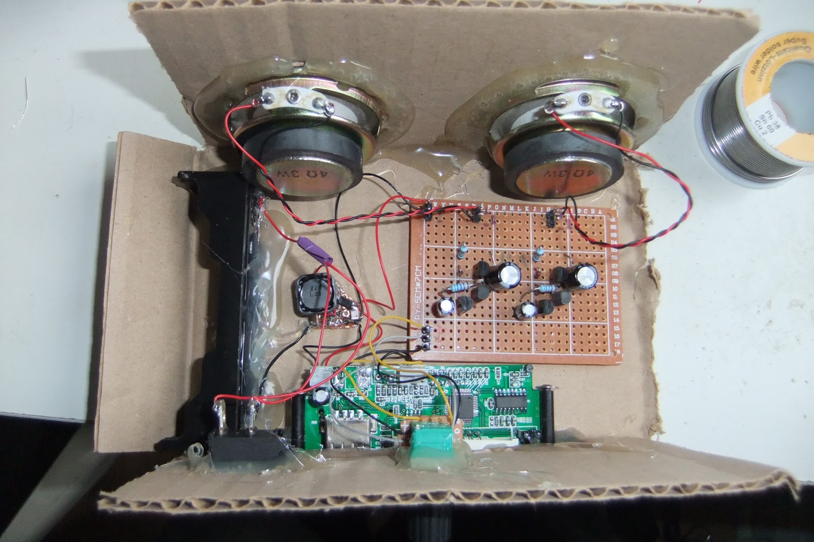
Push-Pull / class AB amp try-out
The PAM8403 PCBs took quite long to arrive, so I started building a push-pull-transistor amplifier for first tests - it's less efficient, but at least I could test if the rest of the setup works. (In fact a friend 'forced' me to do it, for learning/education sake; thanks Andre, it worked. I now see capacitors not solely as equivalent of a battery anymore, but also as a frequency dependant resistor. Well done, sir!)
As always, clicking on the pictures will increase their size.
The layout of the DIY Class AB-amplifier circuit.
Top view - it's quite small, too! It's actually amazing how simple it is to build.
Some more photos and explanations from the build process:
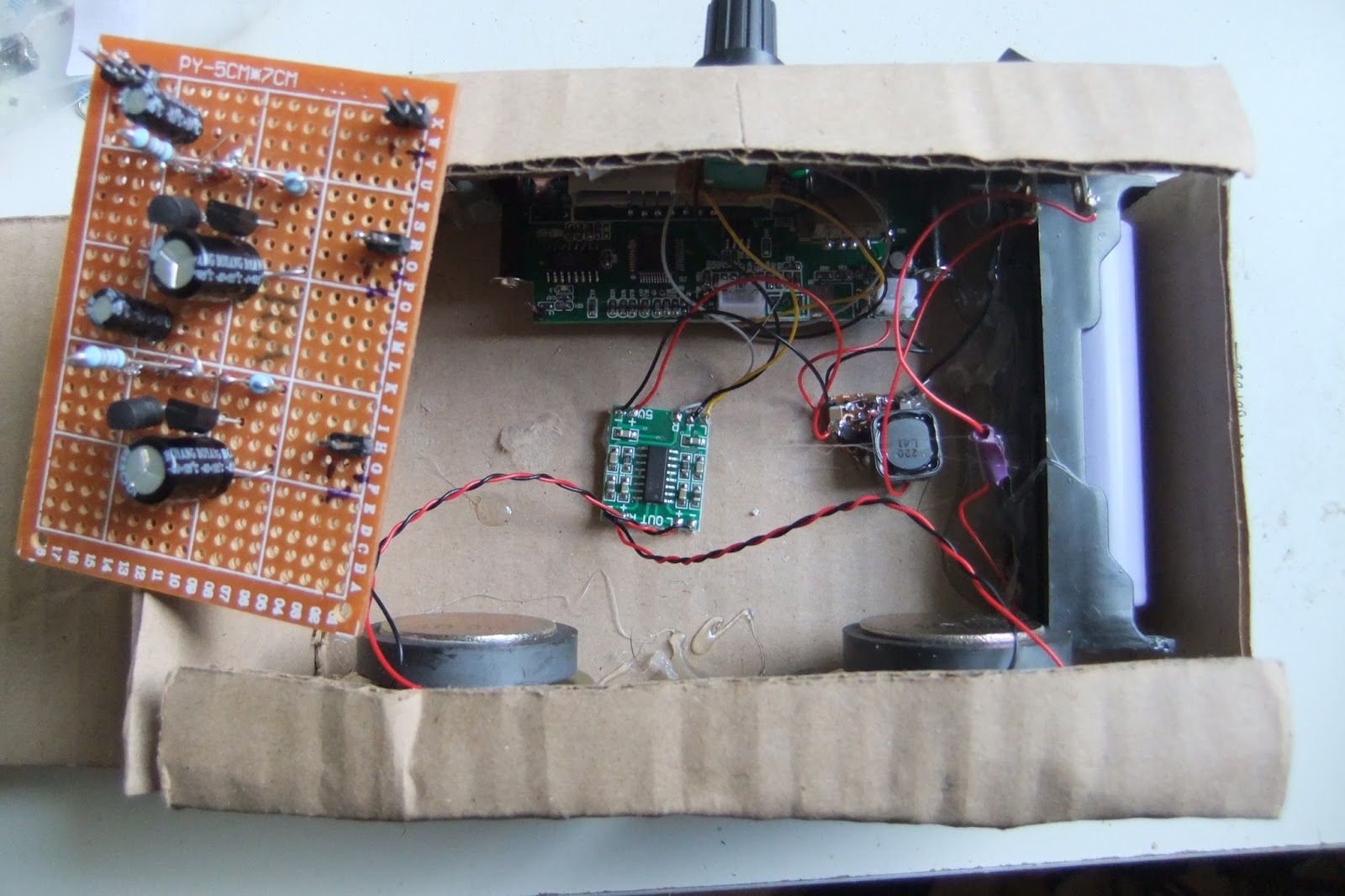
The decoder board had a 78M05 low dropout regulator which I needed to desolder; I just bridged the remaining Vin/Vout terminals. The 5V supply stem from a small TD8208 step-up regulator. As it can deliver up to 2A, this will be enough for the 2 * 3W of the PAM8403 amplifier and the little supply current needed by MP3 decoder board. So the whole Boombox will run with a stable supply when using a LiIon cell.
The MP3 decoder output inspected via DSO toy oscilloscope. Vpp is bigger than 1V. And also notice: It works!
Since I lack craftmenship capabilities, I used simple cardboard for putting the stuff together so far. The output of the MP3 decoder passes through a 20kOhm stereo potentiometer so the output volume will be adjustable.
Hot glue is working very well to keep the components in place.
Since the step-up PCB and the MP3 decoder will draw small amounts of current even in off-mode, I added an on-off-switch between the positive terminal of the battery and the positive input of the TD8208 board.
Not pretty, but working. The display is running multiplexed at a quite low frequency, thus not the whole information is readable with a too short shutter time of the camera.
Then connected everything together. The best thing is it worked immediately! Well, kind of. The volume was a bit too low and the sound distorted. Reviewing everything I found that I soldered the PNP transistor the wrong way - it needs to be emitter against emitter. After that change - wow, that is loud! And the sound quality is nice, too. Except for the prominent hissing noise / white noise at low volume.
And then the PAM8403 PCBs arrived. Soldered one board in unmodified for a first fast test. Have a look at its small size compared to the AB-amp!
So the first draft version of the Boombox can be closed now. This is the front view. Need to decorate it a little, it already looks a bit like No. 5 or Wall-E :)
And this is the back view. I added some Velcro to 'the lid' so the battery can be easily accessed. But since I plugged the cell in a few days ago, its voltage just dropped by 0.2V to 3.9V even with prolonged usage (with the AB amp before as well, no recharge done since plugging it in the first time). The circuits thus are very efficient.
According to the PAM8403 datasheet, even if the Class D amplifier is working filterless, some components should be added to reduce EMI. In all cases, the power supply should have added capacitance of about 1000µF. I didn't want to add electrolytic capacitors as they tend to age, so I used two additional 100µF ceramic capacitors in parallel.
Next Diodes Inc. suggests to use ferrite beads in the lines to the loudspeakers and also 220pF capacitors to ground. This shouldn't be needed for wires less than 20cm long, but well - I don't want to disturb the neighbourhood with a 2*3W sender (the PAM amp switches with 260kHz and the harmonics of this frequency will be disturbed).
Update 25.09.2015: Now with some denoising - the signal lines to and from the potentiometer were receiving noise from other components. The MP3 decoder board isn't shielded at all, so over a layer of capton tape I added some copper foil and soldered it to GND as well, like the copper foil around the potentiometer wires. The PAM8403 PCB got 100µF and 10µF additional ceramic capacitos for proper decoupling. The GND and positive connections of the step-up-boards are done via ferrite beads. The cables for the GND and plus connections of the TD8208 stepup are thicker now. An additional step-up (BL8530) now supplies power to the MP3 board and is fed directly from the LiIon battery as well. This leads to massively less noise. Make sure to have some shielding in place and make the wires as short as possible.
Oh, and using a CD75 4,7µH power inductor instead of the 22µH for the TD8208 decreases noise quite a lot. The datasheet just has some complex formulas for calculating a suitable dimension and makes no suggestions about the proper range for the inductors.
Next step for improvement is a so-called Pi filter between the step-up boards and the periphery. This is a simple solution with ferrite beads, where I added 1µF ceramic capacitors between the + and - lines - one before and one after the ferrite. This helps filtering quite a lot of humming and noise, too.
Now I'm satisfied as the sound quality is very acceptable for a mobile MP3 speaker.
Update 03.10.2015: Finally, the improved wooden version of the PAM8403 mobile Boombox in action. Please bear in mind that the cellphone microphone doesn't have adequate frequency response and the real sound is different, it is actually really good. Depending on the location where you put the box the sound even improves as the sound body will be extended. On a closed bucket, the bass is much more pronounced, for example. The box is loud enough to fill a huge room like kitchen or living room so that the people in there need to shout in order to understand each other! :)
Update 30.09.2015: Today my new saw, some glue for wood and some wood arrived. As the proof-of-concept works, it is time to make a more solid enclosure. Now waiting for the glue to dry so I can continue. :)
Update 01.10.2015: And now nearly finished. Everything is working and the sound significantly improved.
Still no real beautiful design object, but far better than being made only out of cardboard.
Only little left on the todo-list. Fix the battery, add a USB-charger (I think I have a few ;) ). And maybe make a lid from wood to, either to slide in or to flip.
Update 02.20.2015: Done. Charger works. Cotton / wool filling for the empty space to dampen the backward reflections of the speakers massively improves the sound. Unbelievable what this little sucker spits out now. Defined bass, clear heights, very transparent sound. Only a proper lid is missing, it currently is improvised with cardboard again - which is ok, but ... :)
Update 04.10.2015: First real-life test on a big open soccer field. Training for a choreography in dog school, the DIY Boombox had to take care of the music. In 50m distance it was still nicely audible. After two hours of straight usage, the battery voltage fell to 4.04V, starting from 4.14V. That is only very few percent of the battery's capacity (you have to keep the discharging curve of a LiIon battery in mind). Amazing!
And now with a proper lid. Finished! :)
Update 13.11.2015: I'll build three boom boxes - at least, now that several speakers lie around here. This is a Boombox made with Peiying PY-1010C. allegedly RMS 60W. Fed with PAM8403 currently gives nice bass and it is really loud. Have some 2x15W PAM8610 in the reception pipeline, also a TDA7492 amp. For the TPA3116D2 I have some better Blaupunkt GTx 542 SC; that will get a blog article of its own though as the power supply will be interesting there.
Of course, a clip of this beauty at work is available, too. This is during the first test.